
The Austin Universal Windchest |
Pneumatics |
Key
Action |
Stop
Action |
Unit
Action
Video
Files
The Austin Universal Windchest |
Pneumatics |
Key
Action |
Stop
Action |
Unit
Action
Video
Files
The term universal is used in describing these chests because the wind in the chest is contained in a single chamber. The mechanism is attached directly to the topboard, and the wind in the "universal" chest is always available to any pipe on the chest through opening its associated valve. There is no need for wind to travel through a channel to reach the pipe. Within the scope of this definition, an electro-mechanical windchest can also be considered a type of "universal" windchest. Austin chests, however, are distinguished from other types by the type of mechanism used in their actions and occasionally by their size.
Austin Universal Chests are usually made sufficiently deep to allow easy access to the action, which is attached to the underside of the top board. In many cases, the chest is made deep enough to allow a technician to stand inside the windchest when it is being used. From the interior, all parts of the action are visible and accessible.
Austin chests use two different types of pneumatic valves in their actions. The two types differ primarily in the shape of the bellows which provides the motion needed to accomplish the action:
 The diagram to the right
illustrates the action in a rectangular bellows used to control the key action. The
green shape
is
the magnet, as seen from the side. When the magnet is activated, it attracts an
armature, and
that
movement opens a small channel, exhausting its wind. This channel leads to a small
chamber, and
a pouch then collapses, moving a the rod and seal (red in the diagram) and opening a
second
channel. As the rod and seal open the second channel, its wind is exhausted, and the
rectangular
bellows (yellow in the diagram) collapses. As in other types of electro-pneumatic
action, the
channel opened by the magnet is very small so that a strong magnet is not required.
The rod and
seal - - moved by the pneumatic action of the first pouch - - can then open a larger
channel
which
exhausts enough wind to move the bellows.
The diagram to the right
illustrates the action in a rectangular bellows used to control the key action. The
green shape
is
the magnet, as seen from the side. When the magnet is activated, it attracts an
armature, and
that
movement opens a small channel, exhausting its wind. This channel leads to a small
chamber, and
a pouch then collapses, moving a the rod and seal (red in the diagram) and opening a
second
channel. As the rod and seal open the second channel, its wind is exhausted, and the
rectangular
bellows (yellow in the diagram) collapses. As in other types of electro-pneumatic
action, the
channel opened by the magnet is very small so that a strong magnet is not required.
The rod and
seal - - moved by the pneumatic action of the first pouch - - can then open a larger
channel
which
exhausts enough wind to move the bellows.
In the Universal Air Chest, each bellows that is controlled by a key from the console has a wooden tracker attached to it. Through the course of its length, small vertical rods are attached to the tracker, and these are in turn attached to padded metal pallets, which control access of organ wind to individual pipes.
 The way
the motion of the tracker opens a pallet is illustrated in the diagram to the left,
where both
tracker
and vertical bar are colored green. The small pale aqua rectangle above the point
marked
B is the metal stop action bar, shown in cross-section from the end in this
view. In the
position shown,
the stop is on. The pallet is shown in cross section as a red rectangle and
is attached
to
the vertical bar at point B by a metal frame, also shown in red. Although the
framework
of the pallet crosses the vertical bar at point A in this diagram, the two
components are
not attached to one another there. As the bellows collapses, and the tracker moves
to the
right,
the vertical rod pivots at point A. This motion pulls open the pallet, and
air can exit
the
chest through the hole in the topboard.
The way
the motion of the tracker opens a pallet is illustrated in the diagram to the left,
where both
tracker
and vertical bar are colored green. The small pale aqua rectangle above the point
marked
B is the metal stop action bar, shown in cross-section from the end in this
view. In the
position shown,
the stop is on. The pallet is shown in cross section as a red rectangle and
is attached
to
the vertical bar at point B by a metal frame, also shown in red. Although the
framework
of the pallet crosses the vertical bar at point A in this diagram, the two
components are
not attached to one another there. As the bellows collapses, and the tracker moves
to the
right,
the vertical rod pivots at point A. This motion pulls open the pallet, and
air can exit
the
chest through the hole in the topboard.
 When the stop is turned off,
the
metal rod has the position shown in the diagram to the right. In this case, as the
bellows is
exhausted and the tracker is pulled to the right, the vertical bar pivots at point
B, the
only place where the pallet framework and the vertical bar are attached. No force is
exerted on
the pallet and its framework, the hole in the topboard is not opened, and the pipe
above it
cannot
sound.
When the stop is turned off,
the
metal rod has the position shown in the diagram to the right. In this case, as the
bellows is
exhausted and the tracker is pulled to the right, the vertical bar pivots at point
B, the
only place where the pallet framework and the vertical bar are attached. No force is
exerted on
the pallet and its framework, the hole in the topboard is not opened, and the pipe
above it
cannot
sound.
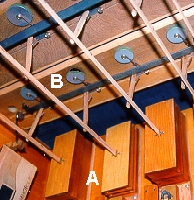
 The
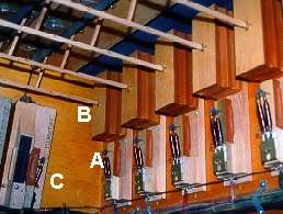
photograph to the left is of a corner of the interior of an Austin Universal Chest.
80 In this view, five
key action units (marked "A"), each of which consists of a bellows at the top
and a
magnet and valve below, are visible along one side of the chest. Each of the key
bellows has a
tracker attached to it (B), and short vertical rods extend upwards from the
trackers. At
C, along the adjoining wall of the chest, is the first of a row of stop action
units.
The
photograph to the left is of a corner of the interior of an Austin Universal Chest.
80 In this view, five
key action units (marked "A"), each of which consists of a bellows at the top
and a
magnet and valve below, are visible along one side of the chest. Each of the key
bellows has a
tracker attached to it (B), and short vertical rods extend upwards from the
trackers. At
C, along the adjoining wall of the chest, is the first of a row of stop action
units.
 The photograph to the right
shows a slightly different view of a similar set of key action units. In this view,
The photograph to the right
shows a slightly different view of a similar set of key action units. In this view,
 In the photograph immediately
above, the dark line that runs slightly up and to the right (between the pallet and
the vertical rod), is a metal bar that forms part of the stop action of the organ.
The motion of
the
stop action is represented graphically in the diagram to the right. The metal bar,
as seen from
the
side, is illustrated by a light aqua rectangle. The darker shape connects it to a
wedge-shaped
bellows shown in yellow. As the wind is exhausted from the bellows, the L-shaped
connector
pivots at the point marked A. The metal rod then pivots at the point marked
B, and its lower edge is raised toward the front as the rod rolls along it top
edge.
In the photograph immediately
above, the dark line that runs slightly up and to the right (between the pallet and
the vertical rod), is a metal bar that forms part of the stop action of the organ.
The motion of
the
stop action is represented graphically in the diagram to the right. The metal bar,
as seen from
the
side, is illustrated by a light aqua rectangle. The darker shape connects it to a
wedge-shaped
bellows shown in yellow. As the wind is exhausted from the bellows, the L-shaped
connector
pivots at the point marked A. The metal rod then pivots at the point marked
B, and its lower edge is raised toward the front as the rod rolls along it top
edge.
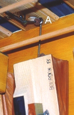 The photograph to the left
shows one of these units in the off position. The bellows is inflated, and the point
at which
the
connecting rod pivots is marked A, as in the diagram above.
The photograph to the left
shows one of these units in the off position. The bellows is inflated, and the point
at which
the
connecting rod pivots is marked A, as in the diagram above.
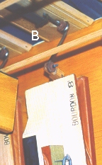 The photograph to the right
shows the same stop unit in the on position. The bellows has been exhausted of wind
and is
collapsed. The metal bar has pivoted at the point marked B, and it is in its
raised
position. The stop controlled by this unit (an 8' Bourdon) is "on," and motion by
any tracker
that
crosses the stop action would cause a pipe to sound.
The photograph to the right
shows the same stop unit in the on position. The bellows has been exhausted of wind
and is
collapsed. The metal bar has pivoted at the point marked B, and it is in its
raised
position. The stop controlled by this unit (an 8' Bourdon) is "on," and motion by
any tracker
that
crosses the stop action would cause a pipe to sound.
In a so-called "straight" chest, a separate unit is not required for each pipe. A single unit controls the action for each stop, and each key also controls a unit. If a manual chest has 61 notes and ten stops, 71 different units are built. The trackers for each key action unit run perpendicular to the metal stop rods, and a pallet is located at each point at which a tracker crosses a stop rod. The Austin chest is also suited to unit actions, in which a separate action unit is required for each pipe.
The photographs below show an Austin unit-action pallet and bellows. The pallet is attached directly to the side of a wedge-shaped bellows that moves when wind is exhausted from it. The first photograph shows the bellows inflated and the pallet closed. The second shows the same bellows deflated and the pallet open.
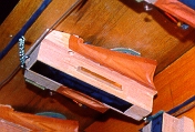
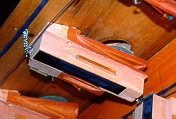
Because trackers and stop rods are not used in the unit action, these units can be placed at any point on a chest. They are often used for pedal stops when large pipes must be placed apart from the rest of a rank. As in other types of unit actions that use electrical switching, control of the specific action-unit by both stop controls and keys is governed by a system of precise electrical switches.
© 1998 James H. Cook