

Mechanical Action |
Key
Movement |
Rollers
and Roller Boards |
Squares
Video
Files
The terms mechanical action and tracker action are often used interchangeably to identify a mechanical connection between key and pallet in instruments that have slider and pallet chests. The designation refers specifically to type of connection in which no electric or pneumatic power is employed in opening the pallet. The name tracker derives from one of the two common connections between key and pallet:
![]() If, however, the key is hinged in the
middle, a sticker is attached to the other end of the key. When the
key is pressed,
the sticker moves up, and a change of direction from up to down is needed to open
the pallet.
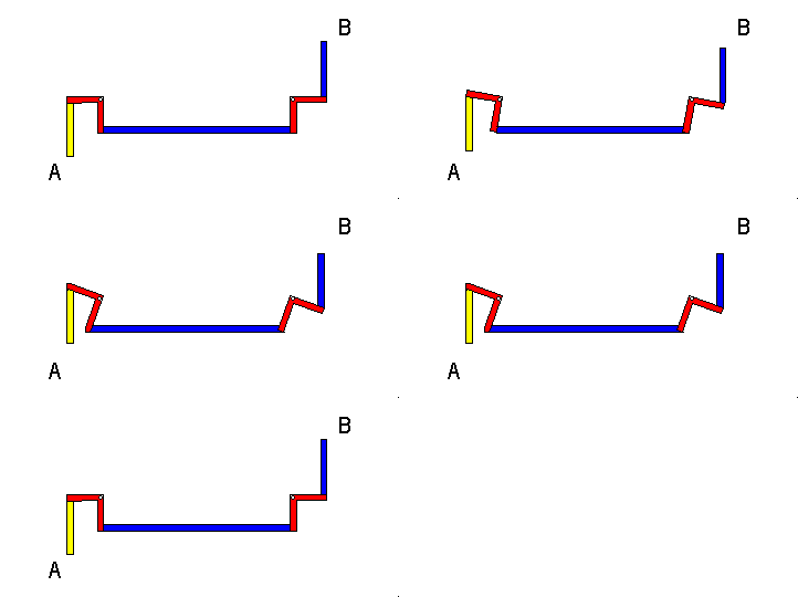
The simplest solution is through the use of a backfall, like the one shown in
the diagram
to the right. As the key is played by being pressed down at point A,
the sticker
(shown in yellow for identification) moves up. The backfall (green in the diagram)
moves in a
direction opposite to that of the key, so that a tracker (blue in the diagram) moves
down at point
B. (The range of motion is exaggerated in this and other diagrams on
this page
for clarification.)
If, however, the key is hinged in the
middle, a sticker is attached to the other end of the key. When the
key is pressed,
the sticker moves up, and a change of direction from up to down is needed to open
the pallet.
The simplest solution is through the use of a backfall, like the one shown in
the diagram
to the right. As the key is played by being pressed down at point A,
the sticker
(shown in yellow for identification) moves up. The backfall (green in the diagram)
moves in a
direction opposite to that of the key, so that a tracker (blue in the diagram) moves
down at point
B. (The range of motion is exaggerated in this and other diagrams on
this page
for clarification.)
If all pallets were located in a straight line from the key that controls them, trackers, stickers and backfalls would be all that is required in mechanical action. However, keys are not always aligned vertically or horizontally with the pallets they control. Even in an organ with only one manual whose chest is located above the keyboard, only one or two keys can control a pallet that is located directly above them. The typical keyboard is thirty-three inches wide, while the usual manual chest is over eight feet wide. Additional mechanisms are needed to transfer the action laterally, so that even if the pallet for middle c is located directly above the key, the lowest c, which may be several feet to the left, can also be played.
Moreover, if an organ contains more than one division, the chests must be located in different positions, sometimes behind one another, or even behind the organist as he or she sits on the bench. In these and other cases, two additional devices are commonly used to transfer the action from the key to the pallet:
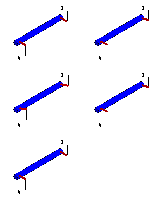
A roller is a small cylinder fastened to a frame at each end so that it is free to rotate about its center axis. In older instruments a roller is made of wood; in newer ones a roller is usually a lightweight, hollow aluminum cylinder. A roller is used to transfer the action from a key laterally, so that a pallet attached to a key does not have to be directly in line with that key.
 In the diagram to the right, a
downward force from the key at A rotates the cylinder (blue in the
diagram).
As the cylinder rotates along its entire length, the other end (B) also
moves.
Short arms at either end (dark red) are attached to the ends of the cylinder and are
fastened to
trackers, the one at A from the key, the one at B leading
to the
pallet box.
 An instrument usually has a series of rollers mounted on a
roller board, in order to accommodate the increasing lateral distance from
pallet to key the farther one moves from the center of a keyboard. The photograph to
the left, for example, shows a section of a roller board attached to a chest for a
small Positiv
division.
108
In this section, metal trackers from the key are attached to the rollers at the end
to the left, while trackers attached to the right end of each roller lead to the
pallets in the chest above. Some indications have been added to the photograph to
make identification easier.
 An arrangement similar to a roller board is used for
to move sliders in
instruments that have mechanical action for stops.
The photograph to the right shows a set of sliders (indicated by the green A)
controlled by a mechanical connection to a stop knob. The rather large rollers in
the lower left portion of the photograph are connected at B to the stop knobs.
This connection is made through long rods whose end can be seen as the light-colored
horizontal bars above the letter B. At C the rollers are connected to
the sliders, and the specific slider to the right of the letter C is in the on
position. The "rollers" for stop control are often installed in a vertical position,
in which case they are called trundles. In spite of the difference in name,
their function is the same as a roller, and their motion can be understood in the
same way.
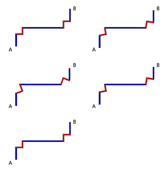
 A Square is used to
change the direction of the motion from a key. A square is usually made of a
lightweight
material such as aluminum, and, in spite of its name, it is typically only an
L-shaped partial
outline of a true square. In the outline to the left, the squares are shown in red,
trackers in blue,
for clarification. The squares pivot at their corners, so that a downward pull at
A from the key is transferred to point B. The up and
down
movement of the tracker at A is transferred to a "to and fro motion" by
the first
square. The second tracker then moves the second square, and it then moves the third
tracker in
the line, so that at point B the pallet can be opened.
 The photograph to the right
shows a set of squares for a manual division in an instrument with mechanical
action.
67 The squares are made of aluminum, and the trackers
of a synthetic material. The trackers that extend downward at the left of the
photograph lead to the keys, and those that extend upward at the right lead to the
pallets. The squares shown here are part of the action of a divided Great
division, and the one on the end is for the top key on the C# side of the
division. The other squares in this set continue down in whole steps from that note.
When the corresponding keys are played, the squares move as shown in the animation
above.
 combination of stickers,
squares and trackers can be used in two ways:
© 1998 James H. Cook