
Introduction |
Electric Power | Pneumatic Power
Experiments with electric magnets and electric motors in the late nineteenth century led to the development of several different applications of the then-new technology to the organ. The introduction of low-voltage direct current to organ action resulted in a fairly standard modification of the keyboards so that they controlled electrical switches. Thus, when a key is pressed, a circuit is closed and the switch that the key controls is turned "on." Stop controls were also modified in this way, so that a knob was attached to a switch that did not itself control a part of the action, but activated another device that then turned a stop on or off at the chest.
Standardization of the keyboards and stop controls in this manner did not lead to standardization of the rest of the organ's action, however. Several different methods of applying electrical power to organ action were developed, and surviving instruments can be found which still successfully use some of these systems. By far the most common types of chest and action developed in the late nineteenth century involved the use of both electrical and pneumatic power to control the movement of organ wind from the chest to the pipe. The most successful of these applications are still in use at the end of the century in various types of electro-pneumatic or "EP" chests.
In all types of electro-pneumatic chests, the two sources of power are used in these ways:
Developments in the application of electro-pneumatic power to organ action have continued, and today there are two primary types of electro-pneumatic chests in use:
Each of these chests is described in a separate page of this tutorial. Two sections below explain the basic applications of both electrical and pneumatic power in all three types of electro-pneumatic chest. These sections explain only the basic principles involved in using electricity and pneumatic power to move parts of the organ's action. However, the use of these actions in actually directing wind to a pipe is different in the three types of chest mentioned above. The specific application of these mechanical to producing sound from a pipe is explained only in the associated pages for each type of chest.
With very few exceptions, all types of electro-pneumatic chests today use a common form of electro-magnet to initiate the action. The magnet is shaped like a horse-shoe or the letter "U," allowing both poles of the magnet to be in contact with the same surface. The magnet is attached to a plate that has a small opening in it to allow wind to pass between the poles. A small metal disc - - the armature - - rests below the poles of the magnet, blocking a second opening. In other words, wind can pass between the poles of the magnet into a small chamber or wind channel, but it cannot leave the chest entirely because the armature blocks the exit.
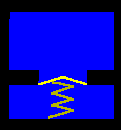
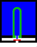 The graphic image to the
right illustrates the motion of the armature when the magnet is activated or turned
on by a key or
a stop control. The two spaces outlined in black represent two areas of a chest.
Organ wind in a
chest is represented in the upper section of the diagram by the color blue. It can
flow between the
poles of the magnet (shown as a green inverted "U") and enter the small horizontal
chamber
below the main part of the chest. When the magnet is turned on (shown by a brighter
shade of green), the poles attract the armature - - a red rectangle as seen in this
cross section
view. When the magnet pulls the armature into place, the armature blocks the flow of
wind from
the chest, but at the same time opens a vent in the lower chamber. When that
happens, the wind
in the lower chamber can escape; in common terminology, the wind is exhausted
from the
lower channel. When power to the magnet is turned off, the armature is released, and
wind can
once again enter the chamber, but it cannot exit through the vent.
The graphic image to the
right illustrates the motion of the armature when the magnet is activated or turned
on by a key or
a stop control. The two spaces outlined in black represent two areas of a chest.
Organ wind in a
chest is represented in the upper section of the diagram by the color blue. It can
flow between the
poles of the magnet (shown as a green inverted "U") and enter the small horizontal
chamber
below the main part of the chest. When the magnet is turned on (shown by a brighter
shade of green), the poles attract the armature - - a red rectangle as seen in this
cross section
view. When the magnet pulls the armature into place, the armature blocks the flow of
wind from
the chest, but at the same time opens a vent in the lower chamber. When that
happens, the wind
in the lower chamber can escape; in common terminology, the wind is exhausted
from the
lower channel. When power to the magnet is turned off, the armature is released, and
wind can
once again enter the chamber, but it cannot exit through the vent.
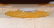
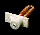 The photograph to the left shows a magnet and
cap
usually found in electro-pneumatic chests that use a form of pitman stop
action.
95 The cap contains both the armature and the
first
sections of wind channels through which air is directed. The hole in the center of
the cap is the
channel through which wind is exhausted when the magnet is activated. The entire
assembly is
small; the bracket and cap attached to the magnet are approximately 1
7/8" X 3/4 ".
The photograph to the left shows a magnet and
cap
usually found in electro-pneumatic chests that use a form of pitman stop
action.
95 The cap contains both the armature and the
first
sections of wind channels through which air is directed. The hole in the center of
the cap is the
channel through which wind is exhausted when the magnet is activated. The entire
assembly is
small; the bracket and cap attached to the magnet are approximately 1
7/8" X 3/4 ".
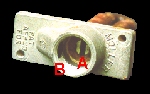 The same magnet is shown to the right with its cap and
armature
removed. The dark space above the red letter A is the opening that leads into
the
windchest between the poles of the magnet. The dark space above the letter B
leads to
the channel to which wind is admitted when the magnet is turned off.
The same magnet is shown to the right with its cap and
armature
removed. The dark space above the red letter A is the opening that leads into
the
windchest between the poles of the magnet. The dark space above the letter B
leads to
the channel to which wind is admitted when the magnet is turned off.
.
- A reminder is in order at this point: magnets of the type shown above are not used to move air directly to pipes. Instead, they are used to exhaust the wind from only a small portion of the chest - - from a conduit or channel. As wind is exhausted from a channel, the pressure is reduced, and that reduction in pressure allows the second part of an electro-pneumatic action to take place, as described below
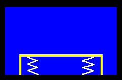
The use of pneumatic power in electro-pneumatic chests exploits differences in wind pressure in separate sections of a chest. Higher pressure in one part of a chest can be used to move components toward a section under lower pressure. These components may be either inflatable bellows or small flexible membranes.
 The diagram to the right
shows an application of pneumatic power to move a small leather membrane of the type
usually
called a "pouch" in EP chests. The blue areas represent parts of the chest that are
under pressure,
and the yellow shape is a flexible horizontal pouch.
When wind is removed from the lower part of the chest, the higher pressure above the
pouch
forces it down, compressing a spring below it. As wind pressure is restored in the
lower section,
the spring can once again move the pouch back into the higher position. The strength
of the
spring and the force of the wind pressure must be balanced: the spring must be strong
enough to
move the pouch into the upper position when both sections are under pressure, but
weak enough
that the wind pressure of the upper part of the chest can compress it when wind is
removed from
the lower part.
The diagram to the right
shows an application of pneumatic power to move a small leather membrane of the type
usually
called a "pouch" in EP chests. The blue areas represent parts of the chest that are
under pressure,
and the yellow shape is a flexible horizontal pouch.
When wind is removed from the lower part of the chest, the higher pressure above the
pouch
forces it down, compressing a spring below it. As wind pressure is restored in the
lower section,
the spring can once again move the pouch back into the higher position. The strength
of the
spring and the force of the wind pressure must be balanced: the spring must be strong
enough to
move the pouch into the upper position when both sections are under pressure, but
weak enough
that the wind pressure of the upper part of the chest can compress it when wind is
removed from
the lower part.
 The photograph to the right shows a pouch from an
electro-pneumatic chest that
uses the type of magnets shown above.
96 The white circle in the upper center of the
photograph is the felt pallet, and the tan material is the pouch itself, made of
sheepskin. The
pouch is approximately 2" in diameter, and the pallet only one-third of that size.
The photograph
shows the pallet in its raised position, held in place by a spring beneath it. When
wind is
exhausted from the channel below the pallet, it collapses and moves down the
1/4" to a point level with the frame to which it is attached.
When the pallet and pouch
are in correct position within the windchest, this limited motion is sufficient to
allow wind to enter
the pipe.
The photograph to the right shows a pouch from an
electro-pneumatic chest that
uses the type of magnets shown above.
96 The white circle in the upper center of the
photograph is the felt pallet, and the tan material is the pouch itself, made of
sheepskin. The
pouch is approximately 2" in diameter, and the pallet only one-third of that size.
The photograph
shows the pallet in its raised position, held in place by a spring beneath it. When
wind is
exhausted from the channel below the pallet, it collapses and moves down the
1/4" to a point level with the frame to which it is attached.
When the pallet and pouch
are in correct position within the windchest, this limited motion is sufficient to
allow wind to enter
the pipe.
 A small bellows can also be
inflated or deflated in a similar manner. The diagram to the right shows a small
rectangular
bellows at the bottom of a chest that contains wind under pressure. When the wind is
exhausted
from within the bellows, it collapses. Bellows differ from pouches in that a bellows
is surrounded
on all but one side by organ wind, instead of on only one side, as in the case of
pouches. Pressure
on the sides as well as on the top causes the bellows to collapse.
A small bellows can also be
inflated or deflated in a similar manner. The diagram to the right shows a small
rectangular
bellows at the bottom of a chest that contains wind under pressure. When the wind is
exhausted
from within the bellows, it collapses. Bellows differ from pouches in that a bellows
is surrounded
on all but one side by organ wind, instead of on only one side, as in the case of
pouches. Pressure
on the sides as well as on the top causes the bellows to collapse.
The different types of electro-magnetic chests listed above (pitman and Austin
Universal) use both
electro-magnets and pneumatic power in different ways. To see the
specific application of the two types of power to each of the chests, make a
selection from the
menu to the left.
© 1998 James H. Cook